Top 10 Types of Water Cooled Condensers
Choosing the right Water Cooled Condenser affects efficiency, reliability, maintenance, and operating cost. This guide examines ten widely used condenser types, from shell-and-tube designs to brazed plate, double-pipe, evaporative, and seawater-compatible systems. Each design removes refrigerant heat differently. Each also creates different demands on water quality, pressure drop, space, and cleaning access.
Experienced HVAC engineers rarely select equipment from a catalogue alone. They check entering water temperature, condensing temperature, flow rate, fouling risk, and the required approach temperature. A condenser operating beside a cooling tower may face mineral scale, algae, and seasonal water changes. A compact plate unit can save floor space, yet its narrow passages may block faster than a shell-and-tube model. Small details matter.
Thermodynamics pioneer William Thomson, Lord Kelvin, wrote, “When you can measure what you are speaking about, and express it in numbers, you know something about it.” That principle remains practical today. Measured temperatures and pressure readings often reveal problems before failure occurs. Still, no ranking is universal. The “best” Water Cooled Condenser depends on load profile, water chemistry, refrigerant selection, maintenance skills, and local operating conditions. Some comparisons look precise but hide uncertain assumptions. That weakness deserves attention. By reviewing these ten types, readers can compare construction, performance, service requirements, and realistic application limits before making a technical decision.
Classification of 10 Water-Cooled Condensers by Construction and Heat Duty
Top 10 Types of Water Cooled Condensers
Classification of 10 Water-Cooled Condensers by Construction and Heat Duty
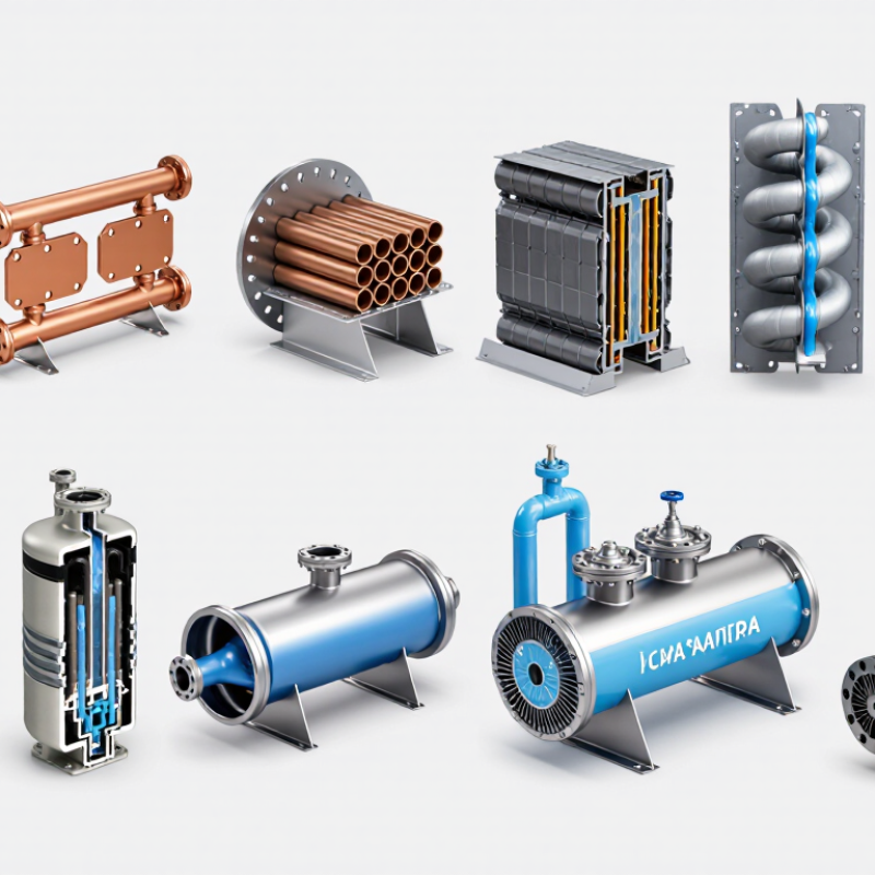
Water-cooled condensers differ mainly in construction, water flow, and required heat duty. Shell-and-tube condensers suit medium to large systems and tolerate steady industrial loads. Horizontal designs simplify maintenance, while vertical designs save floor space. Two-pass and multi-pass versions increase water velocity and heat transfer, but pressure loss also rises. Flooded shell-and-tube condensers keep refrigerant surrounding the tubes, supporting high heat duty. Shell-and-coil condensers offer compact construction for moderate loads. Double-pipe and tube-in-tube condensers work well in smaller systems with limited refrigerant flow. Plate-and-frame condensers provide a large transfer area in a narrow footprint. Brazed-plate condensers handle compact equipment, while welded-plate designs support higher pressure and demanding service.
Heat duty should guide the choice. A small process chiller may need a double-pipe condenser, while a central cooling plant may require a multi-pass shell-and-tube model. Plate designs can respond quickly to changing loads, although fouling may reduce performance faster than expected. This point is often underestimated. Water quality, approach temperature, refrigerant pressure, and allowable pressure drop must be checked together. A condenser that looks efficient on paper may perform poorly with dirty cooling water.
Tips: Keep water velocity high enough to limit deposits, but avoid damaging erosion. Provide removable covers where tube cleaning is expected. Record entering and leaving water temperatures during operation. Small temperature differences can reveal scaling early. In practice, the best selection is rarely the smallest or most powerful unit; it is the one matched to real operating conditions.
Shell-and-Tube and Double-Pipe Designs: 0.5–3 m/s Water Velocity
Top 10 Types of Water Cooled Condensers
Shell-and-tube condensers remain a dependable choice for medium and large refrigeration systems. Their water velocity commonly falls between 0.5 and 3 m/s, depending on tube material, fouling risk, and allowable pressure drop. At 0.5 m/s, slow-moving water may encourage sediment near tube entrances. At 3 m/s, erosion and vibration deserve closer inspection. The ASHRAE Handbook—HVAC Systems and Equipment reports water’s specific heat at approximately 4.18 kJ/kg·K under ordinary operating conditions. This value supports practical heat-load calculations: Q = m × cp × ΔT.
Double-pipe condensers suit smaller capacities and compact installations. Water travels through one passage while refrigerant condenses around it, creating a simple counterflow arrangement. A 1 m/s velocity can provide stable heat transfer without excessive pumping demand, but actual performance depends on diameter and cleanliness. AHRI Standard 550/590 identifies water flow, entering temperature, leaving temperature, and pressure drop as essential rating inputs. These details matter more than catalogue surface area alone. A larger condenser can still underperform when flow distribution is uneven.
Field experience often reveals the weak point. Strainers clog. Valves stay partly closed. Designers should verify flow with calibrated instruments, not assumptions. The 0.5–3 m/s range is useful, but it is not a universal rule. Material limits, local water quality, and seasonal load changes may require a narrower target. Even careful designs need review after commissioning.
| No. | Condenser Type | Main Construction | Typical Flow Arrangement | Water Velocity | Typical Water-Side Pressure Drop | Common Tube Size | Typical Thermal Duty Range | Best-Fit Applications | Key Design Consideration |
|---|---|---|---|---|---|---|---|---|---|
| 1 | Fixed-Tubesheet, Single-Pass Shell-and-Tube | Straight tubes expanded or welded into stationary tube sheets; shell encloses the tube bundle. | Water through tubes; vapor condenses on the shell side. | 0.8–2.2 m/s | 20–80 kPa | 19–25 mm OD | 100 kW–20 MW | General-purpose refrigerant, process-vapor, and utility-water condensing. | The shell side is difficult to mechanically clean; differential thermal expansion must remain limited. |
| 2 | Fixed-Tubesheet, Two- or Four-Pass Shell-and-Tube | Straight-tube bundle with partitioned channel heads that route water through multiple passes. | Counterflow or cross-counterflow with multiple tube passes. | 1.0–2.8 m/s | 40–140 kPa | 16–25 mm OD | 200 kW–30 MW | Installations needing higher water-side heat-transfer coefficients and a compact footprint. | More passes increase pressure drop and can create uneven flow distribution if the channel design is poor. |
| 3 | U-Tube Shell-and-Tube Condenser | Each tube bends into a U-shape, with both tube ends fixed in one tube sheet. | Two-pass water flow through the U-tubes. | 0.9–2.5 m/s | 35–120 kPa | 19–25 mm OD | 300 kW–25 MW | High-temperature service where tube-to-shell thermal expansion is significant. | The U-bend region is difficult to clean internally, and tube replacement is less convenient. |
| 4 | Floating-Head Shell-and-Tube Condenser | One tube sheet is fixed while the opposite tube sheet is free to move inside a removable head. | One-, two-, or four-pass tube-side water flow. | 0.8–2.6 m/s | 30–130 kPa | 19–25 mm OD | 500 kW–40 MW | Large process condensers requiring bundle removal and tolerance of substantial temperature differences. | Higher cost, larger envelope, and more sealing components than fixed-tubesheet designs. |
| 5 | Removable-Bundle Shell-and-Tube Condenser | A complete tube bundle can be withdrawn from the shell for inspection, cleaning, or replacement. | Usually two- or four-pass water flow with shell-side vapor condensation. | 1.0–2.7 m/s | 40–150 kPa | 19–32 mm OD | 1–50 MW | Cooling-water systems with high fouling risk or strict maintenance requirements. | Requires adequate tube-pulling space and structural support for the removable bundle. |
| 6 | Vertical Downflow Shell-and-Tube Condenser | Vertical shell with water tubes arranged for vapor flow downward and condensate drainage by gravity. | Water generally upward or downward; vapor and condensate move downward on the shell side. | 0.7–2.0 m/s | 20–90 kPa | 19–25 mm OD | 500 kW–30 MW | Systems with limited floor area and applications benefiting from reliable condensate drainage. | Tube-side venting, water distribution, and access height must be carefully considered. |
| 7 | Horizontal Surface Condenser with Enhanced Tubes | Horizontal shell-and-tube body using internally enhanced or externally enhanced tubes to increase heat-transfer area. | Cooling water inside tubes; steam or refrigerant condenses outside the tubes. | 1.2–3.0 m/s | 50–180 kPa | 16–25 mm OD | 1–100 MW | Large steam-cycle and process-condensing systems where shell volume must be minimized. | Enhanced surfaces may be more sensitive to fouling, plugging, and unsuitable mechanical cleaning methods. |
| 8 | Straight Double-Pipe Condenser | One pipe is installed concentrically inside a larger pipe, creating separate fluid passages. | Preferably countercurrent; vapor condenses in the annulus or inner pipe. | 0.8–2.5 m/s | 20–100 kPa | 25–100 mm OD inner tube | 5–300 kW | Small refrigeration packages, laboratory equipment, and modular process skids. | The design becomes uneconomical for large duties because many parallel units may be required. |
| 9 | Hairpin Double-Pipe Condenser | Two concentric pipes connected by a return bend, forming a compact two-pass exchanger. | Countercurrent flow in the active legs; condensate normally drains toward the outlet. | 1.0–3.0 m/s | 40–160 kPa | 25–150 mm OD inner tube | 20 kW–1 MW | Compact packaged systems and services requiring close temperature approaches. | Return bends increase local pressure loss and can complicate drainage and mechanical cleaning. |
| 10 | Multi-Tube Hairpin Condenser | Several parallel inner tubes inside an outer pipe, connected through headers and return bends. | Countercurrent or cross-countercurrent flow with parallel tube circuits. | 0.7–2.8 m/s | 30–140 kPa | 12–25 mm OD tubes | 100 kW–5 MW | Medium-capacity refrigeration, heat-recovery, and process-condensing duties. | Parallel-flow balancing is critical; maldistribution can reduce capacity and promote localized fouling. |
| Typical values are indicative engineering ranges for clean or moderately treated cooling water. Final selection depends on water quality, fouling allowance, allowable pressure drop, condensation temperature, materials, corrosion risk, and applicable design codes. | |||||||||
Plate, Brazed-Plate, and Welded-Plate Types: 3–7 K Approach Range
Top 10 Types of Water Cooled Condensers
Plate, Brazed-Plate, and Welded-Plate Types: 3–7 K Approach Range
Water cooled condensers transfer heat from refrigerant vapor into circulating water. The approach is the difference between condensing temperature and leaving water temperature. A 3–7 K approach usually indicates effective heat transfer and practical equipment sizing. Lower values can improve efficiency, but they often require more surface area, cleaner water, and tighter flow control.
Gasketed plate condensers use thin corrugated plates and removable seals. They provide strong heat transfer in compact spaces. Brazed-plate condensers join the plates permanently, reducing size and leakage points. They suit clean, stable water circuits with moderate pressure requirements. Welded-plate designs tolerate higher pressure, temperature, and more demanding fluids. Their serviceability can be less convenient. That trade-off matters.
Real installations rarely match catalog conditions. Fouling, air pockets, poor water distribution, and seasonal temperatures can widen the approach beyond 7 K. Water treatment needs regular verification. I have seen small deposits raise pressure drop surprisingly quickly. Designers should check flow velocity, allowable pressure loss, refrigerant compatibility, and cleaning access before selecting a plate type. A tight approach looks attractive, but excessive pumping energy can erase its benefit. The range is useful, not a promise.
Spiral, Shell-and-Coil, and Flooded Types: 2–5 K Condensing Approach
Top 10 Types of Water Cooled Condensers
Spiral, Shell-and-Coil, and Flooded Types: 2–5 K Condensing Approach
Water-cooled condensers include shell-and-tube, plate, brazed-plate, double-pipe, shell-and-coil, spiral, flooded, falling-film, plate-and-shell, and tube-in-tube designs. Each type transfers refrigerant heat into circulating water. Selection depends on capacity, pressure, fouling risk, maintenance access, and available water quality.
The 2–5 K condensing approach describes the temperature difference between condensing refrigerant and leaving water. A 2 K approach can improve efficiency, but it demands clean surfaces, stable flow, and accurate sensors. A 5 K approach offers more tolerance. It may also reduce heat exchanger size. Spiral condensers create strong turbulence inside compact passages. This design supports effective heat transfer and can handle some suspended particles. Narrow channels still require careful water filtration.
Shell-and-coil condensers place coiled tubing inside a shell. They are compact and relatively simple to service. Flooded condensers keep the refrigerant side filled around the water tubes. This arrangement provides excellent heat transfer and steady condensing temperatures. However, oil return and refrigerant charge require close control. Operators should check approach temperature, water pressure drop, tube scaling, and outlet temperature during commissioning. Small errors matter.
A practical design may target 3 K instead of chasing 2 K. Lower is not always better. Dirty water, uneven flow, or inaccurate instruments can quietly undermine the calculation. I have seen performance estimates fail because one sensor was installed too close to a mixing point. The lesson is uncomfortable: exchanger geometry matters, but measurement discipline matters just as much.
Top 10 Types of Water-Cooled Condensers
Spiral, Shell-and-Coil, and Flooded Types: 2–5 K Condensing Approach
The chart compares representative overall heat-transfer coefficients for common water-cooled condenser designs. Values are typical engineering ranges expressed as midpoint estimates in W/m²·K; actual performance depends on refrigerant, water velocity, fouling, materials, and operating conditions. A 2–5 K condensing approach is a design target that generally requires adequate surface area, stable water flow, and effective heat-transfer control.
Selection Criteria: 50–1,000 kW Capacity, Fouling, Pressure, and Water Quality
Top 10 Types of Water Cooled Condensers
For systems from 50 to 1,000 kW, condenser selection should begin with actual operating conditions. Common options include shell-and-tube, flooded shell-and-tube, plate, brazed-plate, welded-plate, double-pipe, coaxial, shell-and-coil, spiral, and direct-contact condensers. Shell-and-tube designs often tolerate dirty water better. Plate units provide compact size and strong heat transfer. However, narrow channels can clog quickly when filtration is poor.
Pressure deserves careful attention. Confirm refrigerant design pressure, water-side pressure, temperature, and allowable pressure drop. Fouling can reduce capacity long before a failure becomes visible. Hard water may create scale, while suspended solids can damage channels and increase maintenance. Chloride levels also affect material selection, especially in stainless steel components. In practical commissioning work, water analysis is more reliable than assumptions based on location. A perfect selection rarely exists. The smallest condenser is not always the most efficient choice.
Tips: Request hardness, chloride, conductivity, and suspended-solids data before sizing. Add strainers and provide cleaning access where fouling is likely. For a 50 kW unit, a compact plate condenser may be practical; near 1,000 kW, a serviceable shell-and-tube design may reduce operational risk. Leave a sensible fouling margin. Too much margin, however, can increase cost and reduce efficiency. Review the decision after one operating season.