Skip to content

What Are the Top 10 Electronic Power Transformer Types?

An Electronic Power Transformer does more than change voltage. It helps control how electrical energy moves through equipment, from compact control panels to industrial power systems. The right type can reduce losses, provide isolation, or match a source to a load. The wrong choice may bring excess heat, unwanted noise, or an awkward fit inside the enclosure. Small details matter.

The phrase “transformer type” can describe construction, function, or operating frequency, so categories sometimes overlap. A toroidal unit, for example, describes a core shape, while an isolation transformer describes a purpose. That distinction is easy to miss. This guide introduces ten commonly encountered types, including step-up, step-down, autotransformer, isolation, and high-frequency designs. It explains what each one does, where it is commonly used, and which trade-offs deserve attention.

No single transformer suits every project. Engineers typically compare input and output voltage, rated power, frequency, insulation, temperature rise, and installation conditions. A label alone is not enough; specifications and the manufacturer’s documentation should be checked against the actual load. Even then, selection can involve judgment. Real installations may have limited space, fluctuating demand, or cooling constraints that a simple chart cannot capture. The overview that follows offers a practical starting point, not a substitute for detailed design review.
What Are the Top 10 Electronic Power Transformer Types?

Core Operating Principles and Construction of Electronic Power Transformers

What Are the Top 10 Electronic Power Transformer Types?

Electronic power transformers transfer energy through changing magnetic fields. Their windings sit around a magnetic core, usually with insulation separating primary and secondary conductors. The turns ratio helps set voltage, while switching frequency affects core size and losses. Higher frequency can allow a smaller core, but it also makes winding layout and heat management more demanding.

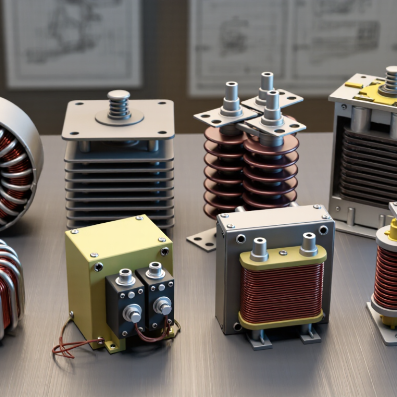
Ten common forms include laminated EI-core, toroidal, ferrite-core, powdered-iron-core, core-type, and shell-type transformers, plus flyback, forward, push-pull, and half-bridge or full-bridge designs. These labels overlap: core shape describes construction, while flyback and bridge names describe circuit operation. An EI core uses stacked steel laminations; a toroid forms a continuous ring. Ferrite suits many high-frequency designs, while powdered cores can store more magnetic energy. Details matter.

In a flyback design, energy builds in the magnetic field during one switching interval, then transfers to the output. Forward and bridge designs transfer energy through transformer action during switching, using different switch arrangements. Push-pull circuits alternate current through two primary sections. Half- and full-bridge circuits drive the primary with switched voltage; a full bridge uses four switches. Gaps, winding order, and insulation affect performance and safety. A neat schematic does not reveal every practical issue. Even a small winding change can alter leakage inductance, and designers sometimes discover that the “best” core is not the easiest one to assemble.
Ten Major Types of Electronic Power Transformers

Electronic power transformers differ by core material, winding layout, and task. Ten useful types are laminated-core, toroidal, ferrite-core, powdered-iron, planar, pulse, isolation, autotransformer, current, and voltage transformers. These categories can overlap: a ferrite-core unit, for example, may also be designed for pulse operation. That distinction is easy to miss when comparing specifications.

Laminated cores commonly handle mains-frequency conversion; their stacked sheets help limit eddy-current losses. Toroidal cores form a compact ring and can reduce stray magnetic fields. Ferrite and powdered-iron cores suit different high-frequency conditions, so check frequency and saturation data. Planar transformers use flat windings for low-profile assemblies. Pulse transformers transfer brief, fast signals or energy. Isolation transformers separate circuits electrically, while autotransformers share part of a winding. Current transformers scale current for measurement; voltage transformers provide a proportional voltage signal. Match insulation rating, temperature rise, load, and switching frequency to the application. A datasheet matters.

Tips: Confirm input range, output regulation, and cooling space before choosing. Check insulation and clearance requirements for the finished assembly. Don’t select by size alone. A compact core may run hot under sustained load, and published ratings depend on test conditions. Verify them.

How Transformer Designs Differ in Voltage, Frequency, and Isolation

Electronic power transformers differ less by appearance than by the voltage and signal they must handle. Common types include step-down, step-up, isolation, autotransformers, control transformers, pulse transformers, high-frequency ferrite transformers, audio transformers, current transformers, and voltage transformers. A step-down unit might convert a high input voltage to a lower supply voltage, while a step-up design does the reverse. An autotransformer uses a shared winding, so it is compact, but it does not provide the same electrical separation as an isolation transformer. That distinction matters.

Frequency changes the design, too. Mains-frequency transformers often use laminated steel cores, with each thin layer helping limit eddy-current losses. Switching supplies operate at much higher frequencies and commonly use ferrite cores, allowing smaller magnetic components. Pulse transformers must transfer brief, fast signals without distorting their shape. Audio transformers instead need to preserve a useful sound range. No core is ideal. Heat, waveform shape, and load can all alter performance.

Isolation is not just a feature name; it depends on winding layout, insulation, and the intended application. A control transformer may provide a lower, steadier voltage for equipment circuits, while current and voltage transformers scale measurements for instruments. Look for the rated input and output, operating frequency, insulation details, and expected load. A transformer can appear correctly sized yet run hot under real conditions. I have found that small wiring and ventilation details are easy to overlook, and they deserve a second look.

Common Applications Across Electronic Systems

Electronic power transformers connect power sources to the needs of specific circuits. Their applications vary with voltage, frequency, isolation, and load. Line-frequency transformers commonly serve power supplies and control panels, while switching transformers support compact converters in computers, chargers, and embedded equipment. Isolation transformers separate circuit sections where electrical separation is required. Autotransformers adjust voltage efficiently when isolation is not needed.

Converter designs use more specialized types. Flyback transformers appear in low- to moderate-power supplies, including standby circuits and small adapters. Forward, push-pull, half-bridge, and full-bridge transformers suit different switching topologies and power ranges. Pulse transformers transmit short control or trigger signals between circuit sections. Small details matter. Core material, winding layout, and operating frequency affect heat, noise, and efficiency, so selecting by type alone is rarely enough.

In a workshop, a transformer’s application becomes tangible: a warm enclosure, a faint hum, or unstable output can point to mismatched design conditions. These clues are useful, but they do not replace measurements. Engineers check load behavior, insulation requirements, temperature rise, and switching waveforms before choosing a part. The categories overlap, and no single type fits every system. Even experienced designers can underestimate stray capacitance or cooling needs; reviewing those assumptions early can prevent costly redesigns.

Key Factors for Selecting the Right Transformer

Selecting a transformer starts with the load, not the catalog. What will it feed? A motor, lighting panel, or sensitive control circuit each has different demands. Record the required input and output voltages, frequency, phase, and expected load in kVA. Leave suitable capacity for starting current and future growth, but avoid oversizing without reason; a lightly loaded unit may operate less efficiently.

The installation environment narrows the choices. Dry-type transformers can suit indoor spaces where containing insulating liquid is undesirable. Oil-immersed designs may fit outdoor or higher-capacity installations, provided cooling, containment, and maintenance needs are addressed. Check ambient temperature, dust, moisture, ventilation, and available floor space. Measure the route to the site, too. A unit that fits the electrical schedule may not fit through the doorway.

Efficiency and electrical quality matter over years of operation. Compare losses at both typical and peak loads, and check whether harmonics from variable-speed drives or electronic equipment require special consideration. Isolation, autotransformer, and control types serve different purposes; they are not interchangeable shortcuts. Protection settings and short-circuit ratings should match the wider system. A neat specification sheet can still miss a practical constraint, so verify assumptions with a qualified electrical professional before ordering.

What Are the Top 10 Electronic Power Transformer Types? - Key Factors for Selecting the Right Transformer

The types below are common transformer designs and functions used in electrical power systems. Categories can overlap—for example, a three-phase unit may also be oil-immersed and step-down. Ratings and applications vary by design, standards, and project requirements.

Transformer Type How It Is Classified Typical Applications Main Advantages Key Considerations Selection Factors
Oil-Immersed Transformer Insulation and cooling method; the core and windings are immersed in insulating liquid. Outdoor substations, utility distribution, and many medium- and high-voltage installations. Effective heat transfer; widely used across a broad range of ratings. Requires liquid containment and fire-risk controls appropriate to the site; inspection and fluid maintenance may be needed. Cooling class, fire and environmental requirements, containment provisions, installation location, load profile, and maintenance access.
Dry-Type Transformer Insulation and cooling method; windings are cooled by air rather than immersed in insulating liquid. Commercial buildings, hospitals, schools, and indoor installations where liquid containment is undesirable. Avoids insulating-liquid leakage and can be suitable for indoor locations when correctly specified. Heat dissipation and ventilation are important; operating conditions and enclosure design affect performance. Indoor or outdoor location, ventilation, ambient temperature, enclosure rating, noise limits, fire requirements, and available space.
Single-Phase Transformer Electrical phase configuration; operates on a single-phase supply. Residential distribution, small commercial loads, and single-phase branch or service applications. Can suit smaller or single-phase loads and may be installed as an individual unit. Not suitable for directly supplying three-phase loads without an appropriate system arrangement. Supply and load phase, voltage, kVA demand, starting or inrush current, regulation, and protection requirements.
Three-Phase Transformer Electrical phase configuration; serves three-phase power systems. Industrial facilities, commercial buildings, and utility transmission or distribution networks. Well suited to three-phase loads and can provide a compact solution for many larger power applications. Winding connections and grounding affect voltage behavior, fault response, and system compatibility. Three-phase load, kVA rating, primary and secondary voltages, vector group, grounding, harmonics, and system fault level.
Step-Up Transformer Voltage function; raises voltage from the primary side to the secondary side. Generating stations and renewable-energy installations connecting generation to higher-voltage networks. Enables power transfer at higher voltage, which can reduce current and associated transmission losses for a given power level. Insulation coordination, high-side protection, and system grounding need careful design. Generator output, grid connection voltage, kVA or MVA rating, impedance, tap range, insulation level, and protection coordination.
Step-Down Transformer Voltage function; lowers voltage from the primary side to the secondary side. Substations, building service, industrial distribution, and equipment power supplies. Provides a lower voltage suitable for downstream distribution or connected equipment. Must be matched to the load voltage, demand, and expected operating conditions. Primary and secondary voltage, load kVA, phase, voltage regulation, tap settings, short-circuit withstand, and future load growth.
Autotransformer Winding arrangement; primary and secondary circuits share part of a winding. Interconnecting systems with similar voltage levels, voltage regulation, and some motor-starting applications. Can be smaller and use less winding material than an equivalent two-winding transformer for suitable voltage ratios. Does not provide galvanic isolation between input and output; suitability depends strongly on the voltage ratio and system design. Voltage ratio, isolation requirements, grounding, fault-current effects, load duty, and applicable electrical codes.
Isolation Transformer Electrical function; uses separate primary and secondary windings to provide galvanic isolation. Industrial control circuits, sensitive equipment, maintenance areas, and applications requiring circuit separation. Separates input and output circuits and can help manage certain grounding and noise concerns when correctly installed. Isolation alone does not guarantee surge protection, voltage regulation, or protection from every electrical hazard. Required isolation level, voltage and kVA, electrostatic shielding needs, grounding scheme, transient environment, and safety standards.
Distribution Transformer Power-system role; supplies utilization-level distribution circuits from a distribution network. Utility distribution networks, local substations, and customer service installations. Designed for distribution service and commonly selected to match local network and customer-load requirements. Load variation, installation environment, and network configuration influence efficiency and service life. Peak and average demand, voltage, phase, impedance, cooling, taps, losses, mounting arrangement, and local utility requirements.
Power Transformer Power-system role; generally used for higher-capacity transmission or substation applications. Transmission substations, generating stations, and major industrial power systems. Supports bulk power transfer and interconnection between system voltage levels. Typically requires detailed planning for transport, installation, protection, cooling, and maintenance. MVA rating, voltage ratio, system stability, impedance, cooling class, insulation level, tap changer needs, losses, and site conditions.